To begin with, let’s understand the purpose of each type of light actor,
SkyLight
The SkyLight actor works better for ambient and bounce lighting because that is what it was designed for. It is like two hemispheres, one upper and one lower, with each hemisphere being like a dome that casts all of its rays inward to the center. This better simulates ambient and bounce light (radiosity). A SkyLight has both an upper and lower set of properties for brightness and color. The upper properties simulates light coming down from the sky and bounced among geometry. The lower properties simulates reflective bounce off of the ground etc. for underside lighting of geometry. The upper and lower values should be set appropriately to simulate the correct environment and time of day. For example mid-day sunny can be yellowish for upper and bluish for lower, night time moonlit can be whitish for upper and purplish for lower. Brightness is usually real low such as 0.05. Note : the location of this actor in the world isn’t important.
DirectionalLight
The DirectionalLight actor is to act as your main light source. You may use more than 1 DirectionalLight & set them in in some custom channel for affecting specific world geometry. DirectionalLight are in the CompositeDynamic channel so each additional DirectionalLight placed in the map adds another map-wide light source on all dynamic objects which can impact render time for the LightEnvironment. A DirectionalLight is also essentially an infinite XY plane that is infinitely far away, causing it to emit parallel rays, and since there is only one sun in our solar system, a single DirectionalLight provides the most accurate lighting simulation for a sun or moon lit environment. Feel free to use them if you are creating a map with binary stars for suns. Brightness is usually between 1 and 3 for the main DirectionalLight actor, depending on overall map brightness desired and whether the highly lit areas are to go into bloom. For lots of bloom go with 4 to 12 range. Note that many custom maps use 2 to 8 DirectionalLight pointing in a different direction to obtain a more polished lighting. Additional DirectionalLight brightness is usually rather low such as 0.05 to 0.5. Note : as the skylight, the location of this actor isn’t important since it is the direction set in the ‘movement section’ of the actor that is counting. Just place this actor with the skylight. Grouping them make it easier to find them.
PointLight
The PointLight actor emit light in all directions. They’re use as a light source for lamps, torches, neons, flares, etc & also light the surrounding areas. Brightness varies depending on the purpose. Still for the best result, it is advise to use a PointLight with a brightness set to 2 to 6 with a small radius for the source & add another PointLight with a lower brightness value like 1 to 0.x with a bigger radius for the surrounding on every light source.
SpotLight
The SpotLight actor emit light in a cone shape in a specific direction. You can think about them as a flashlight. You can set individual settings for the inner & outer cone.
Moveable lights
Moveable lights are dynamic lights that can move throughout the map. This can be anything from a point light that moves along a path to a spot light that rotates to point at a target. This motion is handled with Matinee.
Toggleable lights
Toggleable lights can be turned on & off during gameplay. This is done trough the use of the ‘Toggle sequence’ object withing Kismet.
1) Vertex & Lightmap (LM) – intro
There is a big difference between those types of lighting model, visually, resources and performances wise. I do not intent to go to deep on how both model works since it’s already well documented on UDN and other valuables sources. That being said, this tutorial will focus on LM instead of Vertex simply because you will obtain a much better look, use less resources and obtain better FPS using LM on SM if it’s made to support LM correctly it in the first place.
UT3 engine use Vertex lighting model by default for all SM actor. The newer Unreal engine (UDK) use LM by default. So for now, I’ll explain how LM look on BSP, after how to enable LM on SM and furthermore how to use advance Vertex lighting if your SM doesn’t support LM.
2) Lightmap – BSP
When creating a new BSP surface, the default LM value is 32. In general, it’s rather dull color gradient wise and lack any kind of descent shadows. Still, for surfaces that doesn’t need great color gradient nor great shadows it does the job. But if you want better color gradient and/or shadows, you’ll have to lower the value from 32 to 16 to 8 to 4 to 2 and finally to 1 by trying all values that fit’s your goal. The available values goes from 65536 to 1. By lowering the number, the better it will look. Be warned that a lower value will increase build time and also the file size a bit. Brief, the more you lower the value, the longer it will take to build the map and file size will increase more. So use those values wisely on surface that worth it! How the engine calculate all this is well explained on UDN and other officials forums. At the opposite, if you don’t need any kind of color gradient or shadows, you can set the value to 65536. This is an example of a small surface playing with the most common values. The example is the BSP wall behind the custom torch :
32 (default)

16

8

4

2

1

2.1) Lightmap – static meshes (SM)
Before going any further about LM on SM, you have to be well informed and check several things.
1 – You must know that many stock SM doesn’t support LM at all and are made to be lighted with vertex.
2 – Even if they’re supposed to support LM (judging by the SM properties in the SM editor), there UV’s are badly made so color gradient and/or shadows will look worst than vertex after a full light rebuild.
3 – Finally even the UV’s properties are fine, you must have at least 1 ‘UV channels’ for a good result.
An example of a SM with a proper and correct LM setup is HU_Deco.S_HU_Deco_SM_Barrel01a (the 3 barrels).

If you look at it in the Static Mesh Editor, by looking the yellow squares, the number of UV channels is 2, the LightMapCoordinateIndex is 1 (many index can be available, some SM will indicate 0 or more than 1 but what is important is that you select an index, 0 – 1 – 2 or possibly more that show a good LM layout by typing the 0 – 1 – 2 or more number) & the maximum LightMapResolution is 64. If you click on the ‘Show UV Overlay’ toolbar button, it will overlay a white square filled with black triangle patch blocks, and you can see that the patches fill up the entire white rectangle area, this is the best LM layout you can get. The patch blocks most not touches the white square & must be inside it, forget it & leave it to vertex if their touching. Now that you know that LM is well supported, the only thing left to do is to set your SM to use LM instead of vertex lighting.

Going in the SM properties, I suggest you use a LM value of 32 or 64. 32 is enough to make any SM look great most of the time & will consume less memory than vertex. A value greater than 64 in this case don’t make any sense since the SM doesn’t support more anyway unless there is some lighting artifact on a SM after a light rebuild. In this case in particular, you can raise the value to 128, 256, etc but do it only if its’ required. The way the engine calculate LM, if you raise the value higher than 64 in this case, it will indeed look a tad better but will consume much more memory. 64 is the max value for this SM so it is advise not to go higher since the LM layout is already very well done it will look great. The LM value is determined in the OverrideLightmapResolution field and make sure that bOverriddenLightmapResolution is enable. Always use the smallest possible LM resolution to get the shadow quality you want. 32 is a good value, it’s not to much & provide good results without consuming to much memory. Even 16 can look great on some SM. Only bigger SM need a LM resolution of 64 or greater & in the contrary of BSP, higher the number, the better it will look. Also, in the properties window since bOverriddenLightmapResolution is checked, it will use the value that you typed. If the value is ‘0’, the editor will use vertex mapping. If you uncheck bOverriddenLightmapResolution, the editor will use the default LM resolution that is listed in the SM editor.
An example of a SM with no LM setup is HU_Deco.S_HU_DECO_Barrier.

If you look at it in the Static Mesh Editor, the UV mapping is well done BUT the number of UV channels is only 1, the LightMapCoordinateIndex is 0 and LightMapResolution is 0. This SM should be left as vertex lighting, so in the SM properties, bOverrideLightmapResolution should be enable, and OverriddenLightmapResolution should be left at 0.
An example of a SM with a bad LM setup is HU_Trim2.S_HU_Trim_SM_LowProfileA_closed_long.

The number of UV Channels is 2, LightMapCoordinateIndex is 1, which are both good. Max LightMapResolution is 64 which is great BUT if you click on the ‘Show UV Overlay’ you can see that LM layout of black triangles is all just a bunch of very small little squares that do not fill the entire white square area, so this SM would require a large LightMapResolution of 512 or 1024 to get good shadows, but that is way too much wasted memory for just this one simple SM. So this SM should be left as vertex lighting.
My advice,
Before you insert any SM into a map, always look at it in the SM Editor, check those :
a) If the UV Channels is at least 1
b) Look at the LM UV Overlay to see if the LM layout was created properly and all of the black triangles fill most of the white square area.
c) If the SM only support Vertex, use the best values to obtain a better look which is explain below
Then you will know whether the SM will look good with LM or not and if you have to set the LM resolution to 512 or 1024 to get good shadows on it, you should decide whether it is worth the extra memory or not. Note that some SM may also have 3 or 4 UV channels and may have the LightMapCoordinateIndex at 2 or 3. If you check the ‘Show UV Overlay’ now you can tell if the layout is good or bad.
3) Vertex – SM
In case the SM doesn’t have an appropriate LM layout, you must rely on Vertex if you want to stay with the stock asset. I’m saying that because you can export the SM in another modeler & build a proper UV layout & import the SM back in the UE. So, in the SM properties, the lighting options I’ll be focusing here are located under \StaticMeshActor\StaticMeshComponent\AdvancedLighting’ section. By default settings for any actor are like this :

For my example, I’m using a custom SM with no LM support. As for the fields :
bUseSubDivisions : Default is True. If false, all Advanced Lighting options won’t be effective.
MaxSubDivisions : Specifies the maximum number of Subdivisions that will be traced when building lighting.
MinSubDivisions : Specifies the minimum number of subdivisions that will be traced when building lighting.
SubDivisionStepSize: The amount of subdivisions used is biased by the size of the SM (or rather, distance between vertices). This sets the step size in Unreal units for lighting traces. By default, the step size is 16, so a very small SM will be clamped by the MinSubDivisions, and a very large mesh will subdivide to the amount specified by MaxSubDivisions.
Right now I’ll just focus on the ‘SubDivisionStepSize’. With this option alone, you can fix a lot of your visual issues. In my examples, I lower this number from 16 to 8 and finally to 1, you can clearly see the shadows of the SM are softened and the lighting detail is averaged more through the entire SM.
16

8


1


Take note that as you change those settings, building time will increase slightly. On a small scene it’s not noticeable. Therefore if you do this on every single SM, it will become very apparent. Most importantly, that method doesn’t substitute a fix for a bad UV layout. If the UV layout is incorrect, the ‘SubDivisionStepSize’ size will do little in helping the overall appearance of the SM.
4) My lighting base setup when building a new map,
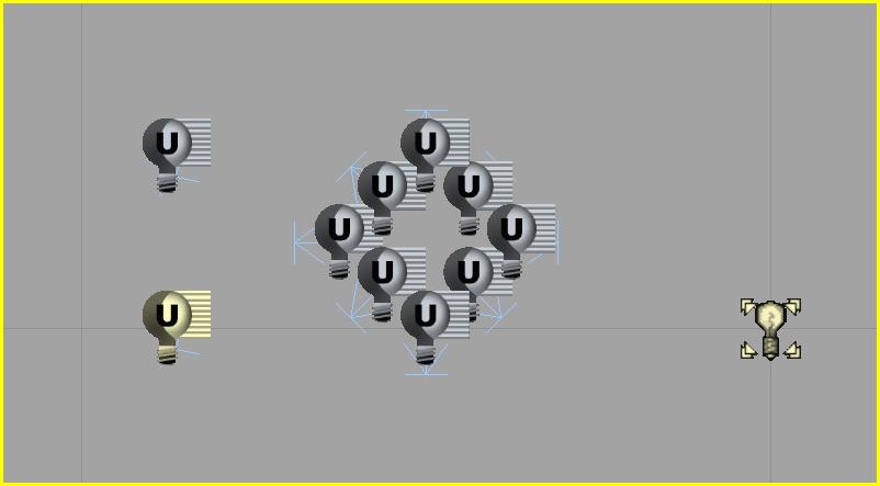
For starting, since the UT3 engine doesn’t directly support ‘global illumination’ or ‘radiosity’, in order to simulate that, you have to set up a multiple DirectionalLight setup. Keep in mind that this will increase your build time and will also impact your FPS a bit, since there will be multiple map-wide lights. The best way to do the main lighting is to set up a group DirectionalLight, one act as the main light source, another one to soften the main shadows and 2 to 8 others that light other angles + a skylight for ambient light. Brief ;
– Add 1 DirectionalLight as the main light source & set the brightness from 1.0 to 3.0 and choose the main color.
– Add another DirectionalLight to soften the main light source with a lower brightness (0.2 – 0.5) and choose the secondary color. Turn off everything that cast shadows.
– Add 2 – 8 DirectionalLight to provide secondary global lighting, each facing outward at increasing 45 degree angle, and select the a complementary color. Drop the brightness to about 0.05 to 0.5 range depending on how bright you want the overall map. The higher you set these, the less shadows you will see from the main light. Disable all shadows again.
– Add the SkyLight to provide just a little bit of ambient light. It has both an upper and lower light setting, which are equal to to the upper hemisphere of the map aiming down and the lower hemisphere aiming up. Common brightness will be around 0.05 to 0.25 range. Daytime ambient light is usually bluish, since it is the sky reflection radiosity. For example :
It take some time to adjust all of the values just right to get the look that you want, but this is the best way to do it with that older version of the engine.
Hope it help and if this as help you enhance your map, I’ll be happy you let me know 😉

Nice tutorial! About the fake GI part, I suggest not to use skylight for indoor environments. I mean not use it at all, even very dim skylight can easilly break the light consistence.
Thanks god we finally have real GI in UE so it’s time to say goodbye to all of these fake ****s 😛
LikeLike
THX 😀
Well, to be honest, not using a Skylight at all will force you to use a plethora of DirectionalLight &/or PointLight &/or SpotLight to do the same job & some areas will still remain pitch black (which isn’t a good thing) since some surfaces of the asset (BSP & SM) won’t be affected by any of the light actor. Also, using a huge amount of DirectionalLight / PointLight / SpotLight affect FPS badly specially when you have a lot of things going on in your map (dynamic lighting, kactor in movement, matches, etc).
I presume that depending of the layout, the size of the map & the look your aiming to acheive, it’s fine not to use it at all 🙂
LikeLike
Nice tut, thank for the knowledge!
LikeLike
THX for letting me know it help you out 😀
LikeLike